The first prototypes of the machine were built on a welded basis, as the final design was still to be decided. Only after about 6 machines a cast iron base was designed and commissioned.
Also the tower encasing the wire drive was welded, with several openings to access the wire brake for the dispensing spool and the wire winding motor.
The first wire diameters that were considered were of 0.25 and 0.2 mm (approx. 0.01" and 0.008" respectively). The spool, on which the wire was delivered was considered too wide, it was approx. 80 mm (3.15"), and it was thought that the alternating movement of the wire during unwinding from that spool would affect the wire tension, considered to be very important since the very early stages. Special spools, both for unwinding and winding were designed and manufactured in house, the former in two pieces and the latter in one single piece. From the original spool, the wire was transferred (on a small lathe) to the special unwinding spools, taking care not to create a tension which would be too strong. This was a tricky operation, where the wire had to be manually distributed from one side to the other of the spool. A constant wire tension during the erosion process was considered crucial since the early stages and it was difficult to find appropriate devices able to compensate and regulate such tensions. Initially, commercially available thread tensioning devices, normally used in weaving machines, were used for that purpose. These tensioning devices were not able to compensate the strong variations which were produced when unwinding from a wide spool. A specially developed mechanism to regulate the wire tension was only later designed, to be used on machines starting with the second generation.
![]()
![]()
![]()
![]()
![]()
![]()
![]()
![]()

|
|
The first wire guides |
Since the beginning, it was quite clear that the wire had to
be guided very accurately, both in vertical as in horizontal direction, in order to produce the desired
results. On the
ram-type machines, where the wire was only used to produce narrow slots or to
separate hard or exotic materials, plastic roller guides
with v-shaped grooves could do the trick. For the DEM 15, special wire guides were designed. The
original design consisted of two sets of two guides, a brass cylinder with two
tungsten carbide pins in it. The actual guide was approx. 1.5 mm (0.06") in
diameter and had a v-shaped groove with a very small bottom radius to
accommodate the wire. This first pin was placed precisely in the center of the brass
cylinder. A few millimeters offset from the center, a second smaller tungsten
carbide pin was mounted, which was used to force the wire into the v-groove. The
guides were mounted above and below the workpiece, one set of two on top and the
same at the bottom, perpendicularly placed to each other, so that the wire was
guided both in X and Y direction. These wire guides were at the same time used
as the current conductors for one pole. The adjustment of the wire guides was a
tricky thing, as they had to be accurately oriented and aligned, and the smaller
tungsten carbide pin should not press too strongly on the wire, as this would have
a negative influence on the wire tension.
The upper wire guiding arm could be adjusted in the
Z-direction so that it could be placed as close as possible to the top surface
of the workpiece.
![]()
![]()
![]()
![]()
![]()
![]()
![]()
![]()
The initial direction of the wire was selected from the bottom to the top through the workpiece, the reason for this was not very clear. After a very short time, it became apparent that this was not very practical, specially with higher workpieces, with pre-machined ones having cavities at the bottom, such as aluminum extrusion dies or even worse, with spinnerets for man-made fibers, where extremely thin wires had to be threaded manually. This threading of the wire was the nightmare of every wire EDM machine operator
Another major problem was the electrical insulation of the various machine parts. On one side there was the moving wire which constituted one electrical pole, and the rest of the machine which was the other one. New materials had to be found which could be machined and were still an isolator and had mechanical stability.
The wire was given the upward motion via two hardened and highly polished steel wheels, which were above the upper wire guides and squeezed the wires to move it on. These two rollers had to be insulated as well to avoid short circuits, a no-go for the EDM process.
Immediately below these two rollers there was a small sapphire pin, connected to a micro switch, sensing if the wire was ruptured and causing the whole process to be stopped, which initially happened all the time, no technology sheets were available yet and all was done by the rule of thumb.
The worn wire was wound up on a separate take-up spool, placed adjacent to the feeding spool. This second spool consisted of two parts, so that the first tip of the wire could be squeezed between the two halves. This fact often produced unwanted effects if not well executed, the wire could get in touch with the steel axis on which the spool was mounted, putting the machine into short circuit and disabling the erosion operation.
![]()
![]()
![]()
![]()
![]()
![]()
![]()
![]()
Initially nobody knew how the ideal flushing should be, submerged or by just spraying the work area with liquid. Therefore, the machine was designed with a container which could be lowered during setup and when the erosion was interrupted. The Soviet machine was equipped with a huge trapezoidal lead-screw, at AGIE, a system with a counterweight and steel wire running over pulleys was selected. With a hand-wheel, equipped with a manual brake, the empty or full tank could be lowered whenever the wire had to be threaded again, a new workpiece had to be placed or the finished work could be removed. Here again, the initial design very soon showed to be unpractical. If the manual brake was accidentally released when the tank was empty, the counterweight dropped to the bottom of the machine base and a long and complicated operation had to performed to put the steel wire back onto the pulleys which had to support it.
Additionally to the submerged bath, four flexible hoses, normally two for the top and the other for the bottom, where used to spray the erosion area directly with dielectric fluid. Since the beginning, deionized water was used for that purpose, the currents used during the erosion process are quite low, not needing a stronger dielectric fluid.
The water, once used, was collected in a container, placed inside the machine base, after passing through a simple paper filter. This container was mounted on small wheels, so that it could be removed from the machine base for cleaning purposes. This obviously had to be done when the machine was stopped. In order for the water to be nonconductive, it had to be deionized with a separate device, filled with a special resin. The water was pumped through that container, which was equipped with an indicator, which measured the degree of conductivity of the water and gave a clue as to when the resin had to be recycled or replaced.
![]()
![]()
![]()
![]()
![]()
![]()
![]()
![]()
|
|
The workpiece
support |
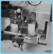
The workpiece was clamped on an angled table, which initially
consisted of two separate pieces of stainless steel, precisely flat and
parallel, held together through centering pins and screws. Only later, a cast stainless steel workpiece
table was designed and commissioned. (The image to the left shows a machine
model already equipped with the first version of a coaxial flushing, enclosing
the wire in a water jet in the working area).
This support was attached to one of the slides producing the
X-Y motions. These slides were accurately guided in two V-guides, with roller
bearings, which were pre-tensioned to increase the accuracy.
The slide for the X-movement was directly mounted on the
machine base, with conical centering dowels and screws. The Y-axis rested on top of it,
again secured by dowels and screws. At the end of both X- and Y-travels, a micro
switch was mounted to secure the interruption of the process when the limit of
the travel was reached.
The axes were driven by stepping motors with the smallest motion unit of 0.002 mm (approx. 0.0008") and a smallest programmable increment of 0.01 mm (approx. 0.0004"). The first machines had no means to communicate back to the controller if the requested movement was really executed, one relied entirely on the stepping motors to do their job, only later, an angular transponder was used to monitor this function. The increments of the stepping motor were transmitted via a set of gears, the one mounted on the lead-screw being built in two halves, preloaded by springs to avoid inversion errors. The lead-screw consisted of a trapezoidal screw with a preloaded bronze nut mounted on the slides.
The gears could be uncoupled so that the slides could be moved via two hand-wheels, very important, as the transverse speed of the stepping motors was extremely slow. On each axis there was a ruler, to roughly establish the position of the axes. The hand-wheels were equipped with movable dials, to set the zero position at the start of the job. This was the only indication at the end of the work, if the program was correct, i.e. if the two dials were back on "0", one could assume that the program was accurate. On later machine models, optional digital readouts could be mounted, which gave a more reliable control.
The very first machine was not yet equipped with a drawing device, this was only added later on, and mounted on top of the Y-axis and where the evolvement of the program could be followed. This "checking device" consisted of a simple piece of sheet metal, on which a piece of paper, fixed by four magnets, was placed. The actual drawing was done by a simple lead pencil fed through a hole in the holding arm above the paper, which was pressed down on the paper surface by a simple heavy nut! It is quite clear that this type of "control" was extremely inaccurate and one had to rely on the dials for more accuracy. Later on, some tests were made using vinyl sheets coated with some kind of wax, on which the contour was engraved with a sapphire pin. This path was then colored with a special ink and the wax was washed away. The result was an extremely thin black line and the vinyl sheet could be put on a profile projector or shadowgraph to check the accuracy of the profile.
Starting with the machines of the first series, a protection
against water sprays was installed above the machining area. This consisted of a
curved hood, made of transparent acrylic glass, which could be lowered during
the machining operations. This device included also a magnetic switch, which was
supposed to interrupt the machining if it was raised. This feature was easily
bypassed, by placing a magnet on top of the wire-drive housing, in the correct
position.
This hood only protected against the water jets which could spray the area
around the workpiece and shower the persons observing the ongoing of the
process. On the other hand it also served as protection for those curious enough
to reach into the sparking area, preventing some electrocutions.
At that time, nobody cared about electro-magnetical radiations, the personnel of the demonstration room on the other hand rapidly found out how this could serve their purpose. An employee of the department producing sample works for prospective customers and living in the absolute vicinity of the company, one day found out that on his transistor radio, if adjusted on a certain frequency, only a hissing sound was heard . He assumed correctly that this was caused by the DEM-15, cutting into some workpiece. From then on, each time that he started a cutting job over the lunch break, in the evening or during the weekend, he set his radio to the known frequency at home, to monitor whether the machine was still cutting or if an interruption occurred either because of a wire rupture or the end of the program.