From here on, it is about mid-1970, the development increased by an enormous amount, the further enhancements of the machine tool, the controller, generator and programming methods followed in ever shorter intervals and went separate ways. At that time, the first Programming department was created at AGIE, in which T.D. and others computed and tested the programs. This publication will only deal with the further enhancements of the programming, as this was the newly adopted field of operations of the author.
![]()
![]()
![]()
![]()
![]()
![]()
![]()
![]()
The first courses in which the programming of the DEM-15 were taught were conducted in several languages, as the number of participants was still very low. For that purpose, the pupils were assembled in a conference room, grouped into languages. The teacher only had an overhead projector (borrowed from another department for the purpose) and a blackboard on which permanently important information was written. No documentation whatsoever was available at that time, only a few drawings or sketches of the shapes to be programmed.
The "pupils" came from every imaginable sectors of the customer's company: proprietors or managers, with or without technical knowledge, machine designers, production planners and machine operators. This meant, that the prerequisites were quire different within the same class. Some had excellent knowledge of mathematics, geometry, square root computations and trigonometry, whereas others almost needed to be taught the basic operations of mathematics.
The only auxiliary tools that were available were some trigonometric and logarithmic tables, which were passed from desk to desk whenever needed. The punched paper tapes were all punched in the AGIECODE, with the simple devices with 8 keys/punches. Initially, the tapes were full of corrected holes, rub-out perforations and spliced pieces of tape.
|
|
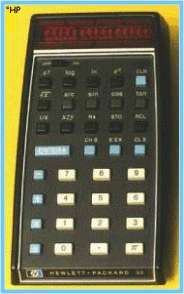
The HP-35 |
During this period, the first pocket-sized calculator came on
the market, enabling the operator to compute a logarithm, square root or any
trigonometric function with a single key stroke, which was almost impossible to imagine.
These computed values could easily be used for further computations, with an
accuracy which was never reachable with logarithmic/trigonometric tables, even
with the most intense interpolations.
The device was manufactured by Hewlett-Packard and named HP-35, because of the 35
keys available on the keypad. This constituted a real revolution in the pocket
calculator market and other manufacturers had a lot to do to produce similar
products and keep abreast.
The purchase of such a unit represented a minor investment, the initial price in
the US market was US$ 365.-- being quite a bit higher in other areas. Due to
this relatively high price, one single unit was purchased, which was
conveniently placed to be accessible by all the pupils whenever needed. There
was even a special cradle, into which the calculator could be locked in, secured
with a key and anchored to a solid object, such as a radiator, to prevent
anybody of taking the valuable item home.
|
|
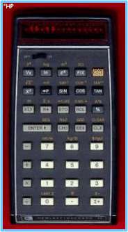
The HP-45 |
After a few months, this first marvel was already complemented or replaced by a follow-up model, the HP-45, with 45 keys and several new functions, making the job of the programmers even easier. These new functions included for example the constant Pi, the conversion from polar to rectangular coordinates, the possibility of using different angular units and the conversion between metric and imperial (inch) units. There were even four separate memories into which computed values could be stored, to be used again in later computations. For the programming classes, four units were purchased, which were distributed to other departments if no training class was scheduled.
Once the paper tape for one programming example was punched, all the participants moved from the training room on the 5th floor to the demonstration room on the ground floor, where one single DEM-15 was available for the testing of the programs. One had to wait until the program in process was either finished or interrupted, to have the machine simulate the freshly punched programs. After having run each tape with a dry run, plotting the contour on a piece of millimeter paper, the participants of the programming class moved back to their desks, to analyze the results and to apply the necessary correction to the tapes. this was a very complex operation, as the punched errors were not easily detectable, and thus taking up quite some time. After correcting the tape, the new tape had to be checked again on the machine, to verify the corrections made to the program.
![]()
![]()
![]()
![]()
![]()
![]()
![]()
![]()
The wire guides were most likely the first components that
were modified relative to the very first design. The grooved tungsten carbide
pins were easily worn, specially if the material to be cut was also tungsten
carbide, the wire itself carried some tiny particles of the eroded material with
it, causing an abrasive action on the guides.
The first enhancements to the guides were still suggested by G.W.
and T.D.,
consisting of two sapphire cylinders of different length but absolute identical
diameter. Each of the two cylinders had a 45� fillet on one side, which had to
be ground to exactly the same value on on both pins. The two cylinders, with the
fillets facing each other, were pressed together inside a hollow brass cylinder,
by means of a small screw, thus creating the groove guiding the wire. The brass
tube was slotted on one side, enabling the wire to get in contact with the
sapphire pins.
The smaller carbide pins, already present in the very first design, were again
used to transfer the erosion current to the wire. It was only considerably later
that wire guides in the shape of half moons were conceived, guiding the wire
even more precisely.
![]()
![]()
![]()
![]()
![]()
![]()
![]()
![]()
It didn't take long for the industry, mainly the punch and
die makers, to request some kind of taper in the dies, enabling the punched
components to drop out of the die. The first machines did not offer this
possibility, a work-around consisted in cutting two plates, a thin one with the
nominal dimensions of the shape, and a thicker one with the shape a tiny bit
wider. These two plates had then to be mounted together, with dowel pins and
screws. The effect reached with this strategy was similar to a tapered die, but
much more complex in its production, as it involved the cutting and assembling
of the two plates.
The first attachment producing some kind of taper consisted of a small device,
mounted on the basement of the machine and having a lever reaching into the
machining area. A small sapphire disk with a small hole in its center replaced
the actual wire guides during this operation, and the lever itself, mounted on
an excenter, "twirled" the wire in a circular movement, thus cutting a
cone rather than a cylinder into the workpiece. The result was quite close to
the requirements, even though the cutting times were much longer, the material
to be removed being much more than in the conventional cut.
A later and more refined version of this device consisted again of a similar
lever mounted on an excenter, but driven by a stepping motor rather then
rotating constantly. The stepping motor received information signals from the
NBY-15, offsetting the wire always normal to the currently cut segment. The
results were a little bit more satisfying, but had some side-effects, such as
the creation of tin bits of scrap material, which could interfere with the
cutting process, causing short circuits.
The problem of the taper cutting was only solved much later, when the first machines were developed, where the upper and lower wire guides were moved independently, again driven by the controller. These movements had to be executed relative to the programmed path, involving quite complex computations inside the NC controller.
![]()
![]()
![]()
![]()
![]()
![]()
![]()
![]()
Shortly after these first enhancements, some changes were also made to the flushing, using a first design of a coaxial flushing, enrobing the wire with water during the cut. This guaranteed much more stable cutting conditions, reducing the number of wire breaks experienced with previous designs.
In order to obtain a better surface finish, a so-called S-box was introduced, with a series of condensers to regulate the cutting intensity in much smaller steps than possible with the basic settings of the STM-D. This device was first mounted on top of the casing containing the wire drive mechanism, and later moved on top of the Y-axis, with the drawing device still on top of it.
After some time, i.e. when the customers using wire EDM were familiar with the process, requests were made to be able to cut larger workpieces. This brought the designers to develop a variant of the original DEM-15, the DEM-15-30, with the travel of one axis extended to 300 mm. As no changes were made to the NBY-15, increments larger than the maximum amount which could be punched in the AGIECODE for the X- and Y-movements (166.65 mm) had to be perforated as two separate sentences.