|
|
|
Who can remember? |
The programming of the first AGIECUT machines was a real
adventure, still remembering that all this happened in 1968/1969, no pocket or desktop
calculators were available yet, being able to compute a sine, cosine
or tangent at the touch of a key. In those years, AGIE already had a
"computer department", equipped with a so-called tabulating machine
(IBM),
operating with 80-column punched cards, with card sorter, duplicator and a
printer. The "program" or better to say the operations to be performed
were wired on a panel, via wires and plugs, with fixed functions in
each field and the machine was only able to produce the basic computing
operations.
The very first programs had therefore to be computed in a
very tiresome, long and inaccurate way with the help of a slide-rule, lots of
paper, pencils and an enormous amount of patience.
|
|
|
Who can remember? |
![]()
![]()
![]()
![]()
![]()
![]()
![]()
![]()
The first machines could only be programmed in the proprietary AGIECODE. This code was developed exclusively for the AGIEMERIC and was extremely concise and simple.
 |
|
The original AGIECODE |
Some special printed circuits were developed only later, to allow the machine to be programmed in either ISO (ASCII) or EIA code.
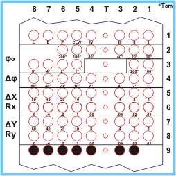
The AGIECODE was a so-called BCD code, for Binary Coding of Decimals. The desired movements had to be programmed by adding the basic values, punching several holes on the same line or frame. For instance, if a X-movement of 107.25 mm had to be executed, the following holes had to be punched: in line #5, holes 8 & 6 (80 mm + 20 mm) and holes 3 & 2 & 1 (4 mm + 2 mm + 1 mm) and in line #6, the holes 6 (0.2 mm) and 3 & 1 (0.04 mm + 0.01 mm).
The number of lines to be punched for one movement, either linear or circular, was fixed and had to be strictly maintained.
The first line of each bloc or sentence contained the basic information of the increment, i.e. if it had to be a linear segment or a circular arc, if it had to be executed with or without erosion current, if it was the last movement of the program, and other additional indications.
If channel #8 of the first line of a sentence was punched, the movement was executed as a straight line, one more hole in channels #1 through 4 indicating the direction of the movement, by selecting the quadrant into which the linear movement was intended. Quadrant #1 was to the "upper right", i.e. with both X and Y in the positive direction, #2 was to the "upper left", i.e. with X negative and Y positive, etc.
If channel #8 of the first line of an increment was not punched, the movement was executed as a circle in counterclockwise direction, as far as channel #5 of the same line was not punched, requesting a circular arc in clockwise direction. The channels #1-4 could not be punched in that case.
Channel #7 was used to determine that the movement shall be executed without erosion, i.e. moving back on the same track, or moving from one opening to the next. These movements were executed with a reference current, to avoid collisions.
The last sentence or movement of a program was requested with a hole in channel #6 of the first line, which caused the controller to end the reading of the paper tape.
If the movement had to be circular, lines #2 and #3 were used to indicate the starting angle Phi zero (φş). This angle had to be measured in the same rotation direction as the circular arc itself, measured from the positive X axis. As indicated earlier, the smallest programmable angular unit was 1° and the holes had to be added to indicate the real value, e.g. a punched hole in channel #1 and another one in channel #3 of line #2 would result in a starting angle of 50°.
Lines #3 and #4 were used for the so-called delta Phi angle (Δφ), or working angle of the circular arc, using the same rules as for the starting angle. When executing a linear movement, lines #2 through #4 were left untouched.
Lines #5 and #6 or #7 and #8 respectively were used to indicate either the length of the linear movement in X (ΔX) and/or Y (ΔY) direction, or the value of the radius for a circular arc. In the latter case, a different value in both directions could be used to produce an ellipse!
In the last line, holes in channels #2 through #8 had to be punched to indicate the end of one segment. A perforation of all 8 holes in one line was considered as a correction perforation, adding one line to the whole amount of lines for one increment or block. Other means of correction, i.e. on an already existing punched tape, could be done by cutting out and sticking a small piece of adhesive tape over the wrong hole and punching a new one in place. For this purpose, most programmers equipped themselves with a small Swiss army knife, with tiny scissors, to cut out the small squares of adhesive tape. Initially, when the tape readers were still electromechanical, this was not so difficult, later, when optical readers were used, either non-transparent adhesive tape had to be used, or one "confetti" had to be inserted on the other side of the tape to prevent the light of going through.
![]()
![]()
![]()
![]()
![]()
![]()
![]()
![]()
|
|
|
|
|
The "Luxus-Puncher" |
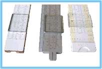
The first devices which were used to punch the program tapes were extremely primitive. It was imperative, that paper tape with pre-punched track holes were used, which was also used to transport the tape. The devices were generally a combination of punching and splicing units, to precisely cut the tape between two track holes and glue it together with another piece of tape. Special adhesive labels were available, a little bit less wide than the 1" of the tape and with all the holes already punched. These holes were a tiny bit wider than the original holes, to facilitate the positioning of the label on the two ends of the tapes.
The small device with the single punch was not the actual first device, the real first one did not have 48 dies and guides but only one single row of 8 holes. Furthermore, it did not dispose of a cutting knife, this had to be done with a scissor, taking good aim to cut precisely between two holes.
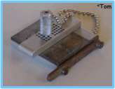
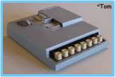
Later on, a small machine with an 8 key "keyboard" was found on the market, with a sprocket wheel to move the tape forward by one step or frame. The 8 keys were used to punch the single channels. The first version of this device was equipped with a fixed sprocket wheel, making it quite difficult keeping track of the number of punched frames, specially when correction perforations (all 8 holes) had to be punched. A later version of the device, modified at AGIE, contained a sprocket wheel with a nonius, which could be adjusted in case of correction perforations. This made the counting of the lines considerably easier.
With this kind of device one had to be careful not to punch again in a location where adhesive tape had been applied to cover a wrong perforation, this would have had a very negative effect on the punches, as the springs which returned them into the home position, were not strong enough to overcome the glue of the adhesive tape.
![]()
![]()
![]()
![]()
![]()
![]()
![]()
![]()
After some time, one realized that companies, which already were equipped with other NC machines, wanted to punch their program tapes with electromechanical devices. These machines were all punching the tape in either the ISO (International Standardizing Organization) or the EIA (Electronics Industry Alliance) code. Therefore also AGIE had to offer the possibility to program the DEM 15 in these two codes, as the AGIECODE could not be punched on those devices.
For this purpose, two printed circuit boards were developed, one for each code, which could be inserted into the controller, replacing the original AGIECODE board. The ISO code was a precursor of the ASCII code, currently used on most computers and allowing both upper and lower case characters, as well as a large number of special characters.
 |
|
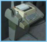
A Teletype
ASR-33 |
 |
|
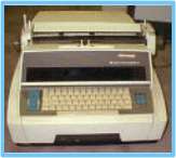
A Friden Flexowriter |
Both ISO and EIA codes were developed in so-called tabulator separated fields, where a tabulator was always needed between each of the entities and each sentence had to contain a fixed number of tabulators. Later machines used so-called "G" and "M" codes.
The very first information on the punched tape had to be the character for program start, "%" in ISO and "h" in EIA and had to appear only in the first sentence of a program. The second field of information contained the three-digit sentence number, which was only used to keep track on a program sheet, it was not interpreted by the machine at all. The third set of data was used to determine whether the movement had to be a straight line (01), a circular arc in clockwise direction (02) or one in counterclockwise direction (03). The fourth field contained the three-digit starting angle (φş) for a circular arc, or nothing in case of a linear movement. The fifth field contained the machining angle (Δφ) for a circular arc or again nothing for a straight line. Fields number six and seven were reserved for the movement in X or Y (ΔX or ΔY) direction respectively for a linear movement (six digits preceded by a positive or negative sign) or for the radius, with the same rules but always positive, for a circular arc. Field number 8 was used to indicate how the movement had to be executed, "01" with erosion and "00" without current, i.e. as a positioning movement. The last filed was used to indicate the end of the program (02). Each program sentence had to be terminated with the characters for carriage return and line feed.
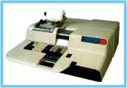
The punched program tapes were produced on machines similar to the ones shown, were the transport or tracking hole was punched simultaneously to the other holes.
The differences between the ISO and EIA code consisted mostly in the codification of the values, the ISO code also had a parity hole, which could be used by the controller as to check if the coded information was complete.
These machines could also be used to duplicate a tape, even frame by frame, to apply corrections.
Programs in the ISO and EIA codes were considerably longer as the AGIECODE programs, but had the advantage that one could print them out on the same device, for checking and archiving purposes. The AGIECODE had to be read by "hand", interpreting each single perforation visually, which was quite tricky and a source of frequent errors.
The increased length also justified an unwinding and winding supplement on the AGIEMERIC, with tensioning rollers to keep the paper tape tension constant. With the electromechanical as well as with the first optical readers, the tape had always to be removed from the reader when rewinding at the end of the program.
![]()
![]()
![]()
![]()
![]()
![]()
![]()
![]()
The computations that had to be performed were totally independent from the code to be used. As mentioned earlier, the very first computations for the programs were made with the help of a slide rule to determine the trigonometric functions.
After a very short time, one could clearly see that this method was not accurate enough to satisfy the requested accuracy of the workpieces to be cut. The next best method was found to be trigonometric tables. Those left over from the school years were also found to be useless, having too few decimal places, the best ones having a mere 4 decimals. After intensive search, a table book was found (Foellmy ?), which listed the functions with an accuracy of 6 or 8 places. This not only for the trigonometric functions but also for the logarithms. These were used to compute the square roots.
It is therefore easily imaginable that the creation of even a simple program was a cumbersome undertaking, having first to separate the contour into straight lines and circles and then to compute the geometric details of each segment. Plenty of paper and lead pencils were needed and of course a systematic step by step procedure. At the edge one should also remember that the lead pencils with a 0.5 mm mine were not available yet, the common pencils had to be sharpened again and again.
The most complex computations were those to determine the angular fractions, both for the starting and the working angles. After quite some brain work, a method was found, to approximate the angular fractions below 1° with a new radius, which had an angular opening of exactly 1° but with a different radius. In some cases a portion of the working angle had also to be "stolen", to prevent the new radius to become too small for the required offset value. After some time, tables were computed, showing which kind of radius had better be reduced rather then increased to obtain the best accuracy.
![]()
![]()
![]()
![]()
![]()
![]()
![]()
![]()
|
|
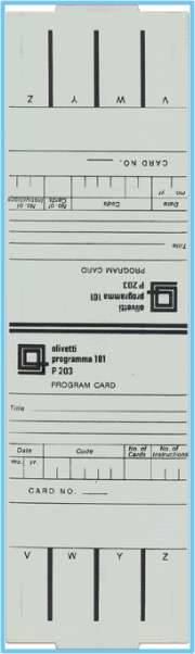
The Olivetti
P-101 |
|
|
The
Olivetti P-101 |
Even though already in the market since 1965, the first calculator which could be used for that purpose, an Olivetti Programma 101, was acquired by AGIE only in late 1969 or early 1970.
This was a machine which can definitely be defined as the precursor of the PC. It could be placed on top of a table, even though not a small one, and it was programmable. Only the four basic operations, addition, subtraction, multiplication and division could be executed, along with the square root and the absolute value.
The program steps to be performed had to entered via a numeric keyboard, along with several special keys to program loops and address jumps, etc. The finished program was then memorized on a magnetic card, with on an approximate size like an 80-column punched card, and which could hold up to 120 programming steps or instructions. The magnetic cards could not hold any values though, and the results of a calculation could not be transferred to a second magnetic card. Therefore, if the 120 available programming steps were not enough, the results had to be printed out and reentered into another program card.
A small wheel was used to select the number of digits to be used for the computing accuracy, the higher that value, the longer it took for the computation. Whilst a program was in execution, a bluish-green blinking light indicated the progress, and a red lamp indicated a computation error, such as register over- or underflow, division by 0, etc. After this, the machine was completely blocked and had to be reset to start another calculation.
Most of the programs were initially prepared within AGIE, by P.F. and T.D., in tedious manual work, mostly done in the late hours or over the weekend. Later, booklets were found, containing programs prepared for other calculations, such as geodetic applications and others. In most cases these booklets came with the recorded magnetic cards, others had to be manually adapted or entered from a list of program instructions.
As the available operations did not include any trigonometric functions, these had to be approximated with repeated loops or iterations. The higher the selected decimal places, the longer this computation took. Then there was the tricky tangent computation, the closer the angle was to 90°, the easier it was for the red light to come on.
The programs for the approximation of the angular fractions had obviously to be created by AGIE, nothing of that kind was available anywhere. In any case, the arrival of this calculator represented a crucial milestone for the two operators (G.W. and T.D.) and allowed an important reduction of the programming time whilst at the same time increasing the accuracy of the machine programs.
![]()
![]()
![]()
![]()
![]()
![]()
![]()
![]()
Additionally to the method described above, to compute approximations to execute fractions of a degree along a circular arc, other "tricks" were developed to overcome the limitations of the NBY-15.
The machine had no built-in "Stop" function, e.g.
to interrupt the erosion a short stretch of contour before reaching the exit
point to secure the part that would drop out when reaching that position. This
function was only introduced later, with the second generation of machines,
using "G" and "M" functions for particular operation.
Prior to the introduction of the following "trick", the machine
operator had always to be in proximity of the machine in order to stop the
process in the right moment. If this was not done, the machine entered into a
short circuit when the contour was finished, as the scrap material moved,
pinching the wire and often causing wire ruptures. Furthermore, the part to be
used could be damaged at the exit point, again due to the movement of the part
that would drop out.
To have such a stop executed automatically, one programmed a linear segment,
into whichever direction, as last sentence (with program end) and as a
positioning movement. Both ΔX and ΔY were programmed as nil movements.
This "stop" was programmed approximately 2 mm before the end-point of
the contour, i.e. as long as the bridge connecting the two components was still
strong enough.
![]()
![]()
![]()
![]()
 |
|
The contour offset |
Another shortcoming of the controller had to be overcome in a
much more complicated way.
The offset feature of the NBY-15 only influenced the values of the radii that
were cut, the straight lines were executed with exactly the same length. This
was quite a restriction, as the lead-in had to be programmed taking into account
the offset value. When cutting dies or other hollow shapes, it was mostly very
important that the offset contour (see the blue path in the sketch) was executed
as a concentric path relative to the programmed one, guaranteeing the perfect
position relative to the starting hole. When cutting punches or other external
shapes without other contour lying inside them, this shortcoming was not so
relevant, one could simply start from the exterior of the material or from a
starting hole, without taking care of the position of the cut contour.
 |
|
The "Caterpillar" |
The selected method consisted in the programming of two small
circular arcs, to be programmed in the sense of execution as the contour itself.
From the starting position, the first arc was programmed (in the example shown
with φş 90°) and a working
angle of 60°, with a radius that corresponded to the maximum offset one
intended to use. The second arc was executed immediately after that (in the
example with φş 210°) and
again with 60° working angle. This produced a kind of equilateral triangular
movement. The real distance between the start point and the contour had to be
reduced by the amount of the programmed radius.
If the lead-in, now consisting of three increments and named "the
caterpillar" was executed with offset ("-" correction, red contour in
the shown example), the whole distance was either shortened or extended by the
value of the offset.
![]()
![]()
![]()
![]()
 |
|
The programmed contour |
Not all the features of the offset function could be overcome
with these "tricks", in some cases the operator had to intervene and
change sign of the correction.
In most cases, with very few exceptions (see "Curiosities"),
the contours were programmed to the dimensions which were indicated on the
workpiece drawing. In the example shown, the green arrow shows the programmed
direction along the shape, the "Ä"
the start point, "¨" the start point on
the contour, and the "©" the stop point.
The real dimensions of the workpiece to be cut, with the necessary clearance (a
die in the shown example) would be reached by selecting the value of the offset
accordingly (see "Contour offset" in this same paragraph).
 |
|
The mirror image, relative to the Y-axis |
If the program was mirror-imaged relative to the positive
Y-axis by requesting all X-movements to be executed with reversed
direction (with the corresponding switch at the back of the NBY-15), this
influenced the direction of execution of the shape as well.
The offset feature of the controller was always based on the path programmed on
the paper tape, meaning that the sign of the correction had to be inverted to
execute the shape on the left side of the sketch. If the operator forgot about
this when pressing "PROGRAM START", the whole workpiece was destroyed
and could be thrown away.
![]()
![]()
![]()
![]()
A further limitation of the controller consisted in the maximum value of the radii that could be cut. This dimension was not limited by the amount that could be programmed in the AGIECODE (166.65 mm) but by the value of the internally stored radius (see "Base circle" in the chapter "The NC Controller"). Therefore, if a radius had to be cut which was larger than 262.144 mm, this had to be achieved with a cumbersome method: one had to decide on the scaling factor to be used on the machine, divide all lengths and radii of the workpiece drawing by the same factor, and set the scale selector to the decided value at the back of the NBY-15. This "trick" carried a penalty with it, as the resolution of the programmable values was also reduced by the same factor.